|
Specification
Emerald provides a range of electric heater batteries and controllers to suit most
air conditioning and ventilation applications.
Sheathed elements provide a clean and safe method of air heating.
These heaters are intended for use in applications where the air leaving
temperature is below 40°C (70% RH db).
The heaters are available in 3 model types:
|

|
|
Circular Duct Heaters
Comprise of a circular duct section manufactured from 0.9 mm or 1.2 mm
galvanized sheet steel
Suitable for ISO standard spiral ducting from 100 mm to 500 mm diameter.
Factory-fitted galvanized sheet terminal box.
Element banks are sized to give a range of steps and phases.
The heater can be connected to the ducting system using flat clamps.
|

|
|
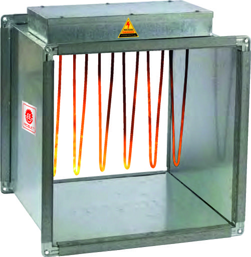
Square & Rectangular Duct Heaters
Manufactured from 0.9 mm or 1.2 mm galvanized sheet steel.
Fitted with 25 mm Ductmate flanges
If width or height < 600 mm: Total perimeter = 1800 mm.
If > 600 mm: Ductmate flanges = 35 mm, perimeter = 1800 mm.
Factory-fitted terminal box and element bank sized to suit duct size and
heating load.
Element box with complete terminal bank is removable for easy
inspection/service without dismantling the duct work.
|

|
|
Elements
Elements are constructed from Nichrome 5 spiral resistance wire surrounded by magnesium oxide power and sheathed in stainless steel, Copper pipe duly chrome plated evenly spread over the open area of the duct and secured into the terminal box. The elements are either linked with a copper bushbar or fitted with a terminal as required to achieve step and phase control requirements.
Heaters are designed to have a black heat surface temperature of 4000c at an air velocity of 2.5m/s
|
|
Panel
Fabricated out of 16G CRC Sheet, duly powder-coated, with the following
controls.
Panel is attached with the heater battery & internally wired with the heater.
Front Panel Controllers.
1. Fan on/off heater rocker switch.
2.
Power on indication.
3.
Heater on indication.
4.
Manual/auto reset indication.
5.
Fan run indication.
6.
Fan failure indication
7.
Door inter lock system
7.
Voltmeter.
Connections
1.
Electric heater battery.
2.
Supply fan.
3.
Temperature sensor via duct or room thermostat.
4.
Airflow switch(normally open)
5.
High temperature cut-out (an integral part of a heater battery)
5.
BMS – on demand.
High Temperature
A high-temperature cut-out is provided:
To protect the system and element bank.
It activates in cases of design temperature excess.
Wired in series to ensure heater shuts down until the fault is rectified.
Manual Reset
This is manually reset once the fault has been corrected.
Auto Reset
Automatically resets once temperature drops to the preset level.
Essential: Ensure fan airflow is maintained; otherwise overheating may occur
Recommended for standard electric heaters.
Auto or manual cut-out can be selected based on design standards.
IMPORTANT
A run on timer must be incorporated into the control system to allow the fan to
run on after the heater has been switched off to dissipate any residual heat.
|
Heater Selection
Calculate heater duty
Output=air volume x constant x temperature rise
Kw=m3/ s x 1.25 x ^t0c
Order Details
When ordering please state the following information
1.
Type of heater- Circular, Duct Mounted, or Stab-in
2.
Air Volume(m3/s)
3.
KW Loading
4.
Electrical Supply (220 to 240)V 1Ph or (380 to 415)V 3Ph
5.
Number of Steps
6.
Duct Size-Width x Height or Diameter(mm)
7.
Vertical Airflow if Required
8.
Any Special Requirements
Care must be taken when positioning the heater to prevent any damage or
overheating of any other equipment in the system.
IMPORTANT
It is the responsibility of the final installation or commissioning person on
site to ensure that all safety control interlocks function correctly and to shut
down systems or part systems as designed to do so, within several seconds of
activation.
|

|
TECHNICAL DATA
Maximum Leaving Air Temperature 400C
Maximum Element Temperature
4000C
Maximum Air Velocity
6m/s
Voltage
(220 to 240)V 1Ph or (380 to 415)V 3Ph
Three Phase Connection
Star connection 3 wire for step control or 4 wires for
thyristor control
Electrical Testing
Flash Tested at 1750 volts for 2 seconds.
Insulation Test
1 Meg Ohm Minimum
Manual
1. Always fit an isolator for
maintenance of the heater.
2. It is important that all
electrical connections are properly made. Elements are tested prior to dispatch
and are within a tolerance of +-71/2 W. If the elements are found to be faulty they can be easily removed and replace. Elements
stored in dap conditions may need drying to attain correct insulation readings.
3. Supply to heater should be
1ph or 3Pgh with Separate neutrals-Refer to nameplate.
4. Cables should be silicone
rubber, Fiberglass or similar high temperature insulated type and be installed.
5. The heater is fitted with a
high temperature cutout which has NC(normally closed) terminals. This must be
connected in series with the main contractor coil circuit, to isolate the heater
in the event of over-temperature(i.e. airflow failure).
6. Ensure sufficient earth connection
to terminal provided.
|